
| |||||

Welding & Heating Chromium Molybdenum (P91) Pipe
As a result of nationwide power emergencies and an abundance of natural gas, 300 to 400 new power plants are projected to be built by the end of this decade. Maintenance and repair of the U.S.'s aging power plants proceeds at a heady pace, too, as utility companies try to keep their units producing at a high capacity.
Whether building a new facility or upgrading an old one, utility companies and designers want to reduce fabrication and materials costs. In addition, utility companies want systems that can withstand higher temperatures and operating pressures to increase operating efficiency and output. To meet these needs, designers are specifying higher-alloyed steels, while fabricators, installers, and contractors must use equipment and techniques that help them work quickly and efficiently.
Advanced Chromium-Molybdenum
While power plants built in the 1970s used 21/4Cr-1Mo steel (P22), today they increasingly use a modified 9Cr-1Mo-V (P91).
"In the past three years we've seen an exponential rise in the specification of P91 for main steam lines, headers, tubing, and heat recovery steam generators [HRSGs] in the United States," says W.F. Newell Jr., P.E., vice president of Euroweld Ltd., Mooresville, N.C., a supplier of specialty welding consumables and equipment. Newell chairs a new subcommittee to write an American Welding Society (AWS) D10 standard for welding advanced chromium-molybdenum steels, including those in the 9 to 12Cr range.
P91 is significantly stronger than P22 at elevated temperatures. P91 typically allows a wall thickness reduction by at least a 2-to-1 ratio. If the wall is thinner, hanger loads are lighter. Also, a wall that is 50 percent thinner takes less time to weld and uses less filler metal.
"From a designer standpoint, it's a wonderful material," says Newell. "From a fabrication standpoint, P91 presents some challenges. Preheat and postweld heat treatment are mandatory and absolutely critical to the service life of the alloy. It is incumbent on the fabricators and installers to learn how to work with it."
Bring on the Heat -- But Control It
Depending on the P91 welding application, codes that apply to power plants and refineries may include ASME B31.1 Power Piping, ASME B31.3 Chemical Plant and Petroleum Refinery Piping, ASME Section I Power Boiler Parts, ASME Section VIII Unfired Pressure Vessels, and ASME Section III -- Division I Nuclear Components.
Welding P91 generally requires preheating the joint, maintaining interpass temperatures, hydrogen bakes, and postweld heat treatment (PWHT). Preheating, typically to 400 to 500 degrees F, drives off moisture and thereby reduces hydrogen. Hydrogen embrittlement can lead to cold cracking of the finished weld. For this same reason, hydrogen bakes are recommended for P91 if a weld cools to ambient temperature before PWHT.
Preheating also reduces the thermal gradient between the base material and weld puddle, and it improves weldability by reducing the heat necessary to make the weld while reducing hot-cracking tendencies.
Welding thicker materials and high-alloy steels usually requires maintaining minimum preheat and maximum interpass temperatures. If a material cools below the minimum temperature between passes, restraint issues may arise or hydrogen may contaminate the weld. If the material becomes too hot, which can happen during multiple-pass welding, some steels can lose their corrosion resistance. With P91, the matter is more practical: higher than 600 degrees, the weld puddle usually becomes too fluid and difficult to control.
PWHT requires controlling temperature in four phases to relieve the stress caused by welding. The following example describes the four phases with P91 and follows ASME B31.1. However, always refer to the appropriate code for procedural details and never work from memory.
1. Control temperature. The weldment usually may be brought to this temperature, generally 600 degrees, without any time constraints.
2. Control-temperature rise. Once the control temperature is reached, the code requires a controlled temperature rise of no more than 600 degrees per hour divided by one-half the maximum thickness, but in no case more than 600 degrees per hour.
3. Soak or hold temperature. This is the stress-relieving temperature. For heavy-wall P91 weldments, that temperature is typically 1,400 ±25 degrees. Other alloys may be between 1,100 to 1,400 degrees. Soak time depends on the thickness of the material. One hour per inch is common for most alloys, but Newell recommends that heavy-wall (greater than 3¼4 in.) P91 components should have a minimum soak time of two hours.
4. Control cool. After the soak time, the material must be cooled at a controlled rate to prevent stressing the part, which could lead to cracking. Typically, the control-cooling rate is the same as the control-temperature rise -- cool from 1,400 to 600 degrees at a rate of no more than 400 degrees per hour. Below 600 degrees, the weldment can air-cool to ambient temperature.
Stress relieving restores ductility. Without ductility at ambient temperature, power piping and other chromium-molybdenum components may not withstand hydrostatic testing and other aspects of fabrication, transportation, start-up, and shutdown phases.
According to Newell, "Prior to stress relieving, it is not unusual to see an as-welded P91 weldment with a Rockwell C hardness in the mid 40s to low 50s and a Charpy V-notch toughness of just 3 foot-pounds. After PWHT, P91 is significantly more ductile. Its Rockwell C hardness drops to the low 20s and its Charpy V-notch toughness can increase to 40 to 70 foot-pounds, depending on the welding process."
Newell says he cannot emphasize enough that P91 provides no forgiveness when fabricators and installers fail to stress-relieve the material properly. It will fail under circumstances that P22 would not.
Also, like most heavy-wall, large-diameter piping, a P91 pipe's inside diameter (ID) and outside diameter (OD) can exhibit a substantial temperature gradient (50 to 100 degrees) if the procedure and technique are not carefully evaluated and qualified, so installers need to bring ID and OD temperatures as close together as possible.
New Induction Technology
Modern induction heating systems can heat parts up to 1,500 degrees. Newer induction heating systems are different from their early counterparts. Induction heating systems of the 1970s used power sources the size of a small car that required enormous amounts of primary power. The old systems also had copper tubes to carry the induction energy and for cooling water flow.
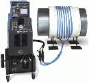
Today's more advanced induction heating systems use compact, lightweight, and energy-efficient inverter technology. Modern induction heating power sources weigh from 165 to 500 lbs., and some can fit on a small, wheeled cart along with a temperature controller and recorder and water cooler (see Figure 1).
(Figure 2) In induction heating, electric current flows through the coil, generating a magnetic field in the part. The rapidly changing magnetic field creates eddy currents in the part, causing heat to be generated. This is similar to the heat generated in a transformer. The coils do not heat up, so welding can be done while the coil is still attached.